|


| |

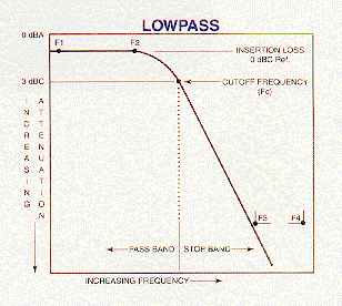
Specifying a Lowpass Filter
Define the following parameters:
- 3 dB frequency, MHz (Fc)
or
- Passband frequency, from MHz (F1) to Passband frequency, MHz (F2)
- Stopband attenuation frequency, MHz (F3)
- Stopband attenuation, dB at (F3)
- Upper stopband frequency, MHz (F4)
- Upper stopband attenuation, dB at (F4)
Standard Design Assumptions:
Impedance: 50 ohms input/output
Passband VSWR: 1.5:1 max.
Transfer Function: 0.05 dB Chebyshev
Temperature Range: -40 to +85 deg. C

Specifying a Highpass Filter
Define the following parameters:
- 3 dB cutoff frequency, MHz (Fc)
or
- Passband frequency, from MHz (F1) to Passband frequency, MHz (F2)
(Must always specify)
- Stopband attenuation frequency, MHz (F3)
- Stopband attenuation, dB at (F3)
Standard Design Assumptions:
Impedance: 50 ohms input/output
Passband VSWR: 1.5:1 max.
Transfer Function: 0.05 dB Chebyshev
Temperature Range: -40 to +85 deg. C
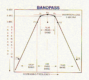
 Specifying a Bandpass Filter Specifying a Bandpass Filter
Define the following parameters:
- Center frequency, MHz (Fo)
- 3dBc bandwidth, MHz (F2-F1)
or
- X dBc bandwidth, MHz (FH-FL)
- Lower stopband frequency, MHz (F3)
- Lower stopband attenuation, dB at (F3)
- Upper stopband frequency, MHz (F4)
- Upper stopband attenuation, dB at (F4)
Standard Design Assumptions:
Impedance: 50 ohms input/output
Passband VSWR: 1.5:1 max.
Transfer Function: 0.05 dB Chebyshev
Temperature Range: -40 to +85 deg. C
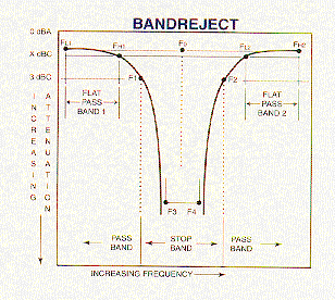
 Specifying a Bandreject Filter Specifying a Bandreject Filter
Define the following parameters:
- Center frequency, MHz (Fo)
- 3dBC bandwidth, MHz (F2-F1)
or
- X dBC bandwidth, MHz (FH-FL)
for flat passbands 1 + 2
- Lower stopband frequency, MHz (F3)
- Lower stopband attenuation, dB at (F3)
- Upper stopband frequency, MHz (F4)
- Upper stopband attenuation, dB at (F4)
Standard Design Assumptions:
Impedance: 50 ohms input/output
Passband VSWR: 1.5:1 max.
Transfer Function: 0.05 dB Chebyshev
Temperature Range: -40 to +85 deg. C
NOTE: When specifying any type of filter, please indicate the type of
connectors required and if there are any restrictions regarding the mechanical
configuration. Please consult the factory if phase, group delay, or time domain
performance must be defined, or the filter must handle a significant amount of
RF power. Additionally, any of the standard design assumptions may be modified,
if required.
|
![[Company Logo Image]](_borders/freelogo.jpg)
